PC221 Analog Electronics I
LC Circuits
Objectives
- To examine inductor charging and discharging
- To examine frequency response of an LC circuit
- To continue measurement of phase in AC circuits
- To continue the use of SPICE circuit simulation
including AC analysis.
- To compare results of analysis, measurement, and simulation.
Equipment
- digital multimeter, bench power, oscilloscope
- various resistors and capacitors and inductors
Procedure
Here we'll look at a slightly different filter circuit.
The difference with this circuit is that it will have a
resonance. In other words VL/V will have
either a maximum or a minimum at a specific
frequency.
You'll be using the circuit shown, with the
components as
follows:
V is a 1V AC sine wave (of varying frequency) source
with a DC offset of 5V, like this:
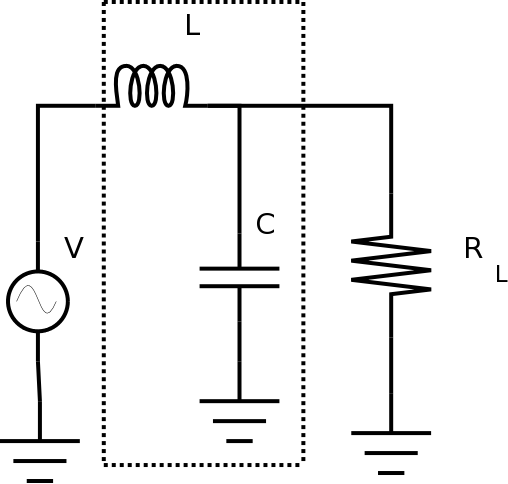
The other values are;
- L = 1.2 mH
- RL = 1.0 kΩ
- C = 10 μF
Circuit Measurement: Digital Multimeter
- Measure the component values with a digital
multimeter, and fill them in Table 1.
Here's a link on
measuring inductance using the TENMA meter.
| Table 1: Component Values and Voltages |
| Quantity |
Measured Value |
Units |
| L |
|
|
| RL |
|
|
| C |
|
|
| V (amplitude) |
|
|
| V (offset) |
|
|
-
Perform all of the same kinds of analysis you did for the RC
filter circuit so that you can compare the results, and present
your results the same way.
Remember to use the measured values from Table 1 for your
calculations and simulation.
Be sure to measure both V and
VL at each frequency in order to find the resonant
frequency. Adjust the input signal, if needed, to keep the same
amplitude at each frequency.
Try to find the resonant frequency as precisely as
possible.
For this reason, use at least 10 points per decade in your
simulation.
Show your results to the lab instructor.
Before you leave the lab, have the lab instructor
sign your lab notebook immediately after your last entry.


