PC/CP200 Electronics Laboratory I
Simple DC Circuits
Objectives
- To understand the operation and applications of a voltage
divider.
- To understand the operation and applications of a
potentiometer or variable resistor.
- To understand the operation and applications of pull-up
resistors.
- To understand the operation and applications of a current
limiting resistor.
Equipment
- digital multimeter, bench power
- breadboard, bare DIP switch or keypad
- various resistors, potentiometer (or "trimmers"), LEDs
Procedure
- Resistors are frequently used to divide voltages into desired
amounts to perform specific functions. A simple voltage
divider is shown below to the left and a more complicated
voltage divider is shown to the right. The numbered terminals are
used as tap points to obtain the desired voltage(s). If nothing
is connected to the terminals, the voltage divider is
unloaded; if a resistor is connected to the terminals,
the
divider is loaded.
Construct the simple voltage divider shown on the left, using two
different-valued resistors with values of several kΩ
each. Use
+12V supply. Measure Vout, and verify that it satisfies
the
voltage divider formula
Vout = Vs x
R2/(R1
+R2).
- Design and construct a voltage divider that divides an input
voltage by three. Use +12V supply.
Demonstrate and explain operation of this voltage divider
to
lab instructor.
- Construct the more complex voltage divider shown on the right
under question 1. Use four different resistor values of several
kΩ each (e.g. 3.3, 5.6, 2.2, 3.9), and a +12V supply.
- Measure the actual resistance for each of the
resistors.
- Measure the voltage drop across each resistor.
- What percentage of the total voltage does each voltage
drop represent?
- Measure the voltage from each tap point to ground. The
tap points are the points numbered 1 through 5.
- How does this voltage divider work? Explain.
- A potentiometer or variable resistor is a
voltage divider with a variable division ratio. The diagram on
the left shows the symbols for a potentiometer. The diagram on
the right (hopefully) makes clear the relationship between a
potentiometer and voltage divider.
(Note: Sometimes a potentiometer is
also called a "trimmer".)
The total resistance of the potentiometer, R1 +
R2, is constant.
The arrow represents a slider or knob which will vary the values
of R1 and R2 subject to the constraint that
the total resistance
does not change. Use an ohmmeter to study the resistance of the
(unconnected) potentiometer. Correlate your observations with the
diagram above. Determine the minimum and maximum values of
R1, R2, and R1+R2.
- Note the numbers on the potentiometer. How do they indicate
the resistance of the potentiometer? Is it similar to anything
else you've seen?
- Using the potentiometer instead of the resistors, construct
the simple voltage divider shown in question 1. How can you tell
which pin of the potentiometer is the wiper?
- Use one of the
small screwdrivers to adjust the potentiometer.
Observe the
effect of the potentiometer setting on the value of
Vout.
What
are the minimum and maximum attainable values of Vout?
How do
they compare to the supply voltage, Vs?
Does the output voltage vary linearly with the adjustment of the
wiper?
-
Modify your circuit to add a "load"
which is small compared to the potentiometer resistance
(e.g. 10 kΩ)
to
the center tap of the potentiometer. Repeat your
measurements.
Demonstrate and explain your results to the lab
instructor.
Potentiometers can be linear, i.e. R2 varies in
proportion to the
wiper's displacement. Potentiometers can also be logarithmic,
i.e. log(R2) varies in proportion to the wiper's
displacement.
The logarithmic potentiometers are popular in volume control
circuits because the perception of loudness follows a logarithmic
law.
- One of the applications of a resistor is to limit
current. Consider the case of a circuit input which will be
controlled by a switch. Proper implementation of switches is
especially important in digital circuits.
Consider the following circuits:
In (a) the input to the buffer gate is directly connected to
the switch. If the switch is closed, the input is connected to
ground and the input is a stable low. However, when the switch
is open, the input floats as it is not attached to any
stable source. Although the input will tend to float high, any
electrical noise could cause the input to go low.
This is not a
good circuit.
In (b) the input to the buffer is directly connected to the
supply voltage, Vs at +5V, to ensure that the input
will not
float when the switch is open. However, when the switch is
closed, there will be a direct connection between power and
ground or, in other words, a short circuit. The circuit will
not work. There will be too much current, too much heat,
goodbye wire! This is not a good circuit.
In (c) the input to the buffer is connected to the supply
voltage, Vs at +5V, through a resistor. This is
called a
pull-up resistor because it "pulls up" the
input and ensures it does not float. When the switch is closed,
the input to the buffer will be pulled low. Although current
does flow from power to ground, it is severely limited by the
resistor.
In a typical digital circuit, Vs is +5V and the
pull-up
resistor is 10kΩ or 47kΩ. Construct a pull-up
resistor
circuit for a switch. The circuit does not have to feed any
gate, simply measure the voltage Vout at the point
the gate
would be connected. When the switch is open, what is the
voltage Vout? When the switch is closed, what is the
voltage
Vout? Calculate the current when the switch is
closed.
Points to ponder after the lab (include in post lab writeup)
- This circuit segment almost looks like a voltage divider.
Is it a special case?
- There is also a pull-down resistor configuration. Can you
figure out what it would look like?
- An LED (light emitting diode) is a semiconductor that emits
photons when a current flows through it. An LED has very low
internal resistance. If you do not use a current limiting
resistor, too much current will flow through the LED and it will
burn up. To a point, the higher the current, the brighter the
LED. Most LED's have a current rating, which determines the
size of the resistor you will need. The current rating tells you
what the maximum allowable current for the part is. General
purpose LED's handle currents in the 10-20mA range.
LEDs are directional (have a positive and negative leg) and are
forward biased because the current must flow from the
positive to the negative. Directional components must be inserted
in the correct orientation for the component to work. For an LED,
very little current can flow in the opposite direction.
Measure the resistance of the LED with an ohmmeter in both
directions.
If the resistance is above the maximum
range of the meter in both directions, try using a different
colour of LED.
Is it easy to tell by the resistance which way the
current should flow for the LED to light up?
The symbol
for the LED, a triangle with a bar at the negative end, may also
include arrows going outward from the object to symbolize the
light.
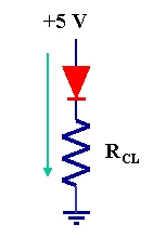 (a)
(a)
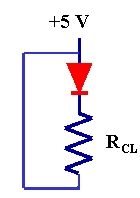 (b)
(b)
The circuit would be set up as in figure (a). The circuit in
figure (b) will not work because there is no current. (Do you
understand why there is no current in this circuit?
Explain.)
Construct a test circuit to light up an LED. Assume the LED
current rating is 10mA unless told otherwise by the lab
supervisor. Show your calculations for determining the value of
the current limiting resistor.
- Construct a simple circuit that has a switch and an LED that
indicates the status of the switch. You decide if open|closed
corresponds to on|off or off|on.
Demonstrate and explain your circuit to the lab
instructor.
- Use any remaining time you might have to practice for lab
test 1.
Before you leave the lab, have the lab instructor
sign your lab notebook immediately after your last entry.
Wilfrid Laurier University
© 2019 Wilfrid Laurier University


