PC/CP200 Electronics Lab I
Function Generator and Oscilloscope
Objectives
A function generator or signal generator
produces a voltage signal with a specified shape, frequency,
amplitude, duty cycle, and DC offset. It's primary purpose is
to produce a known accurate input signal to test a component's
or circuit's response. One lead of the signal generator is
attached to ground and the other(s) provide input to the device
under test.
An oscilloscope, sometimes simply called a
scope, is a device that measures the voltage difference
between the positive and negative probes and displays the voltage
difference as a function of voltage difference against time. The
primary functions of an oscilloscope are to test circuit
performance over time (i.e. meters are good for an instantaneous
measurement) and to compare two signals (e.g. the input to the
circuit against the output from a circuit).
Always make sure that your function generator, your
oscilloscope, and your circuit are properly grounded. If ground is
improperly setup, any results you may see are meaningless.
- To gain familiarity with a function generator.
- how to properly connect a function generator to a
circuit
- how to select the signal shape, frequency, amplitude,
duty cycle and DC offset
- understand how the above signal characteristics are set
on the function generator and how they impact the signal
shape
- To gain familiarity with an oscilloscope.
- how to properly connect an oscilloscope to a circuit
- how to determine the signal's shape, frequency,
amplitude, duty cycle and DC offset
Equipment
- bench power
- breadboard
- 2.2kΩ resistor and .01 μF capacitor for
microphone
circuit
- speaker - two connections: one to ground and one to the input
signal
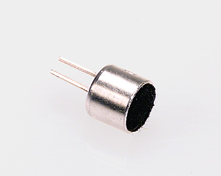
- microphones - this year you will be using the
MD9745APZ-F
- microphones are orientation sensitive
- Microphone Omnidirectional 6.0X5.0MM -- EM6050P-433
[image, datasheet]
- Microphone Electret Condenser -44 ± 2 db --
MD9745APZ-F
[image,
datasheet]
- signal/function generator - instek GFG-8217A
- oscilloscope - one of TDS 210, TDS 1002 (old and new numbers
for the same oscilloscope)
Procedure
Function Generator and Oscilloscope
Introduction
-
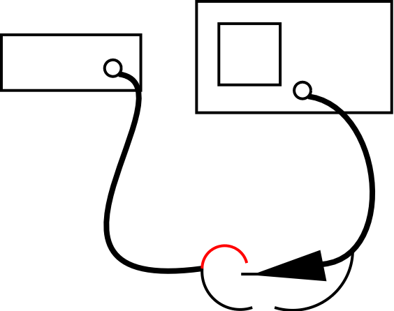
Connect the
signal generator to an oscilloscope as shown below.
(Use a scope probe connected to the scope, and a normal BNC
connector for the function generator.)
Use the signal generator to produce a sine wave at 1 kHz and
peak amplitude of 1 Volt (2 volts peak-to-peak).
Verify the amplitude and
frequency are correct using the scope.
- Play with the trigger settings on the scope to see what
happens. For instance:
- Set the trigger to the channel that's not connected.
- Set the trigger to the channel that is connected, and
then move the level around within the voltage range of the
waveform, and then outside it.
- Try any other trigger settings you want to see what they
do.
After playing around with the settings, use a setting that
displays a stable waveform on the screen.
- With your signal on the screen, see what happens when you change the
"Probe" setting for Channel 1 on the scope to 10X. Does the signal change?
Does the voltage scale for the channel change?
Now, with the "Probe" setting for Channel 1 still set to 10X, set the
switch on the probe itself to 10X. What happened?
Make a note of how the probe switch and the probe setting on the scope
need to go together.
Switch both the probe switch and the scope setting back to 1X.
-
Now that you understand how the oscilloscope works, sketch a
signal in your lab notebook. Include the scope settings and show
how to calculate amplitude, DC offset and period from the trace.
- Notice how the rotary buttons along the bottom of the signal
generator have two different labels; one of the labels applies
when the button is pushed in, and the other applies when
the button is pulled out. See what happens with the
waveform as you test each button so that you understand what
happens each way. After this go back to the required
waveform.
- Wire up a speaker (two connections: one to ground and one to
the input signal) so that you will be able to both hear the sound
of the waveform produced by the signal generator and see the
waveform produced by the signal generator. (The signal
generator is the input to both the speaker and the scope.)
- Did the voltage drop when you connected the speaker?
- By how much?
- What does this tell you?
-
Make sure the signal generator is set to a sine wave output
for this part.
Infants can typically hear sinusoidal signals that range in
frequency from 20 Hz to 20 kHz. Things go down hill as you age.
The fine hairs in your ears that sense sound become brittle and
break off. Usually the smallest hairs break first, making you
lose your ability to hear high frequency sounds. You can speed
this process up, significantly, by listening to loud noises like
gunfire, jet aircraft, and music. Determine the highest and
lowest frequency audio signal you can hear. Sometimes it is hard
to tell if you can really hear a signal or are just imagining it.
Have someone else turn the signal on/off while you are looking
away. See if you can reliably tell if the signal is on or off. Do
this for each person in the group.
Please keep the volume to a reasonable level! How did
you adjust the volume?
- Repeat the experiment above, but using square waves and
triangle waves. Compare the sound of sine waves to square and
triangular waves. Do they sound the same or different? Does your
answer depend on the frequency of the signal? Can you hear the
same range of frequencies for the different wave shapes?
Demonstrate your procedure to the lab supervisor.
Be prepared to summarize your findings.
- Select a square wave on the function generator. What happens
when you vary the duty cycle? Does it affect the sound? How
would you determine the duty cycle from the scope?
- What happens when you vary the DC offset? Does it
affect the sound?; How do you determine the DC offset from
the scope?
Demonstrate your procedure to the lab supervisor.
Be prepared to summarize your findings.
Examining Complex Signals
Disconnect the speaker and function generator for the next
part.
In the following section, do not make
the
mistake of simply connecting the microphone between power and
ground. Only connect it as shown in the diagram on the datasheet.
-
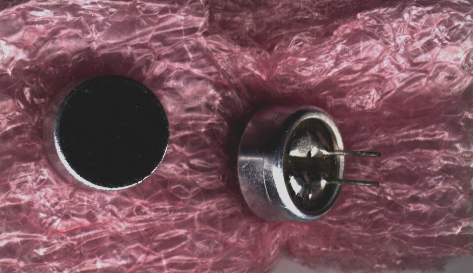
Turn the microphone upside down so that you are
looking at the pins. Note that one pin appears to be
connected to the metal case of the microphone. That pin
must be connected to ground. The microphone subcircuit is
shown in the datasheet and the values for the required resistor
and capacitor are given above.
- In your notebook, redraw the diagram from the data sheet
showing how to connect
the microphone to show that the circuit is actually just a
voltage divider with a capacitor on the output.
Connect the microphone as shown.
- Speak into the microphone ("test 1-2-3-4",
"sound check", "testing") while looking
at the oscilloscope screen. Describe the signals that you
see. How do they compare to the function generator?
What is the voltage of a whisper versus a normal speaking
voice?
- Hum a note, whistle, and/or say a vowel into the
microphone. How do these signals compare to the words
spoken previously?
- Blow on the microphone. Did the oscilloscope show any
response? What does this tell you about how a microphone
works?
Demonstrate your microphone circuit to the lab
supervisor. Be prepared to summarize your
findings.
- If you have time remaining in the lab, practice using the
scope. Learn how to use the scope so that you can turn it on and
find an unknown frequency all by yourself. You, not your
partner! Setup the function generator to produce a sine wave
at 1 kHz. Turn the amplitude about half way up. Measure the
waveform using the scope. Next have your partner adjust all
the settings on your scope so it is totally unreadable and change
the frequency and amplitude of the function generator. See if you
can lock on to the signal. Record the voltage, frequency, and DC
offset using the oscilloscope.
(This is what you'll have to be able to do for Lab Test #4.)


