PC/CP200 Electronics Lab I
Measuring Continuity
|
Measuring continuity
with DMM
(continuity test mode)
|
 |
If the component to be measured is in a
circuit, turn off the power to the circuit and discharge any
capacitors. Any voltage in the circuit will cause inaccurate
readings.
|
 |
- Connect the meter's Red lead to V
Ω input.
- Connect the meter's Black lead to COM input.
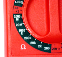
- Set the function switch to
 , audible
continuity test mode, located immediately above
the ohmmeter range. After selecting the continuity test
mode, touching the two probe tips together should produce a
tone. , audible
continuity test mode, located immediately above
the ohmmeter range. After selecting the continuity test
mode, touching the two probe tips together should produce a
tone.
- Place probe tips at either end of the component to be
tested. Do not touch the component or the probe tip with
your hands as your body's resistance will affect the
measurement.
- Continuity is indicated by an audible tone.*
- Turn the meter off when measurements are complete.
* Meter specifications indicate an audible tone when
resistance is ≤ 75Ω.
|
|
Measuring continuity
with DMM
(ohmmeter mode)
|
 |
If the component to be measured is in a
circuit, turn off the power to the circuit and discharge any
capacitors. Any voltage in the circuit will cause inaccurate
readings.
|
|

|
- Connect the meter's Red lead to V
Ω input.
- Connect the meter's Black lead to COM input.
- Set the function/range switch to Ω (ohmmeter) and select the
lowest
measurement range, i.e. 200 Ohms.
- Place probe tips at either end of the component to be
measured. Do not touch the component or the probe tip with
your hands as your body's resistance will affect the
measurement.
- Read the resistance on the display.
- Open circuits (no continuity) are shown as an
overload.
- Short circuits (continuity) will show as
essentially zero resistance.
- Overload indication is normal in the
Ω
range.
- Turn the meter off when measurements are complete.
|
Wilfrid Laurier University
© 2019 Wilfrid Laurier University


