PC/CP200 Electronics Lab I
Logic Gates Characteristics - Current
Objectives
- To gain more experience with an oscilloscope.
- To measure the current characteristics for various digital
logic families.
- To obtain and interpret information from a data
sheet.
Preparation
Gates have current limits as well as voltage limits. Four
particular quantities are of interest:
- IILmin -- the minimum input
current which must be drawn from a gate's input to ground to
pull the input low.
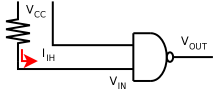
- IIHmin -- the minimum input
current which must be supplied to a gate's input to pull the
input high.
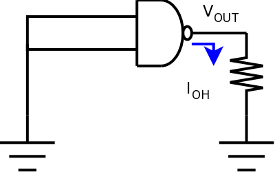
- IOHmax -- the maximum current
which the gate can source through its output and still keep the
output high.
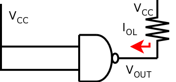
- IOLmax -- the maximum current
which the gate can sink through its output and still keep the
output low.
IILmin and IIHmin may require some
explanation. Most people
assume that if the inputs of a gate are not attached to anything
they will be treated as logic low. This is a bad assumption. An
important piece of information about various logic families is what
happens when inputs are left to float; i.e. remain unconnected.
They may float high, low or anywhere in between. To have an input
recognized as something other than its "floating" state
will require that a finite amount of current be either supplied to
the input (to make it high) or drawn from the input to ground (to
make it low.) Never assume anything about unconnected inputs. If
you want them to be in a particular state, tie them that way. Never
leave inputs
floating.
These current limits are referred to as the fan-in and fan-out
characteristics of digital circuits. In this lab we shall attempt
to measure these.
Definition of terms can sometimes become tricky. An output
limit, for instance, can be seen as either how much is
guaranteed to be supplied, or as how much can be safely
demanded. In other words, the limit can be seen as either
belonging to the device or the surrounding circuit. While they
are functionally equivalent, the first view will give a minimum
for a quantity while the second will give a maximum. Different
manufacturers may take either view, and so it is important to
understand this so that you can make sense of whichever you are
given. In the previous section, these limits were discussed as
limits on the device.
Equipment
Procedure
 |
Great care should be taken to avoid static
discharge into CMOS (static sensitive) based chips. |
Before starting the lab, review the CMOS handling
procedures.
- Always use a ground strap. If your grounding mat doesn't
have two grounding straps, one for each of the partners, see the
lab instructor.
- CMOS devices should be stored pin down in conductive foam
when they are not in a circuit.
- Never leave unused inputs floating; connect to ground or +5V
to prevent excessive current consumption and erratic
behaviour.
- Never connect an input signal to a CMOS device when the power
is off.
Current limits; Fan-out
Do the following analysis (steps 1 to 3) first for
the 74LS00 and then repeat for the 4011.
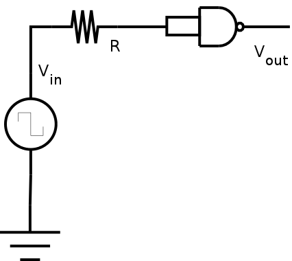
- Wire up the following circuit; R is a variable resistor.

A resistance substitution box is an alternative to using
a trimmer; it doesn't have a wiper, but the resistance value can
be read off the dial; you don't have to measure it.
Use
the oscilloscope to measure Vin and Vout.
Since
one end
of R
is
tied to a known voltage, and the other end is connected to the
oscilloscope, then the voltage across R is known, and thus the
current through R can be calculated using Ohm's Law.
Obtain the value of the output sourcing current
IOHmax from the data sheets. Determine
the maximum value of current which keeps the output in the high
state; i.e.
the
output voltage above the specified value of
VOHmin . Thus determine IOHmax.
Is it within
the manufacturer's specifications?
Demonstrate for 7LS400 to lab staff.
- Now set up the following circuit; R is a variable resistor.
Obtain
the value of the output sinking current
IOLmax from the data sheets. Determine the maximum
value of current which keeps the output in the low state and thus
IOLmax. Is it within the
manufacturer's specifications?
Demonstrate for CD4011 to lab staff.
- Based on your results from voltage measurements above, can
you suggest why this parameter matters; i.e. under what
conditions is the output of a gate going to be pulled high, so
that it has to "work" to keep the output low?
Current Limits; Fan-in
TTL
Do the following analysis for
the 74LS00.
- Wire up the following circuit. Use the oscilloscope to
measure Vin and Vout. Since one end of R, a
variable
resistor, is
tied to a known voltage, and the other end is connected to the
oscilloscope, then the voltage across R is known, and thus the
current through R can be calculated using Ohm's Law.
- Disconnect R, so that the gate input is unconnected.
This means there is no current into
one of the gate inputs. Observe its output. Is it what you
expect it to be? Explain your answer. Hint: What does this tell
you about whether the inputs are being seen as high or low?
- If the inputs of a device “float” so that they
appear to be in a particular state with nothing connected, then
by definition you don't need to supply any current to keep
them in that state! [Sometimes the inputs float to a voltage
which is in the indeterminate region, so that sometimes they will
appear to be high and other times they will appear to be
low.] The TTL and CMOS chip will behave differently.
If the chip can hold the output state without any current, skip
the next step (as changing the current will make no
difference).
- Reconnect R so that you can adjust the current into the gate.
Starting with the lowest current possible, monitor the value of
Vout as current is increased, so that you can determine
when the
output voltage just reaches the specified value of
VOLmax and thus determine IIHmin.
Demonstrate for 7LS400 to lab staff.
CMOS
The inputs to CMOS are capacitive, which is
different than TTL.
While the amount of input current required is very small,
the speed of the gate response will depend on the current
in or out of the inputs.
- Wire up the circuit below, using the decade box for R.
- Adjust the frequency generator to produce a 0-5V square
wave output at 10kHz.
- With the decade box resistance at a minimum, line up the
input and output signals on the oscilloscope.
You may want to invert one of the channels so that you can
overlay them directly.
- Increase the value of R, and see when you observe a delay
between the input and output signals. Measure the time delay, and
record the value of R.
Don't confuse this with the propagation delay; this isn't the
time for the signal to get through the gate, it's the
time for the input capacitance to charge or discharge.
- Given that the time constant for the RC combination is RC,
use the time you have determined to estimate a value for the
input capacitance of the gate.
- Look up the input capacitance of the gate in the datasheet.
Is the value you calculated within the manufacturer's
specifications?
Demonstrate for CD4011 to lab staff.


