PC/CP200 Electronics Laboratory I
Resistive Sensors and Bridge
Circuits
Objectives
Input transducers or sensors convert
one form of energy into a measurable electrical characteristic. For
this lab you will be using two resistive sensors: a strain gauge
and a photoresistor.
- To measure the resistance of a strain gauge over its range of
operation.
- To measure the resistance of a photoresistor over its range
of operation.
- To set up and test a photoresistor using a voltage divider
circuit.
- To introduce the concept of null measurement.
- To set up and test a photoresistor using a Wheatstone bridge
circuit.
Equipment
- digital multimeter, bench power, dual supply
- breadboard
- various resistors, variable resistor
- to make the strain gauge: overhead transparency, sandpaper,
pencil, a pair of alligator clips
or
use an existing strain gauge on a transparency
- photoresistor
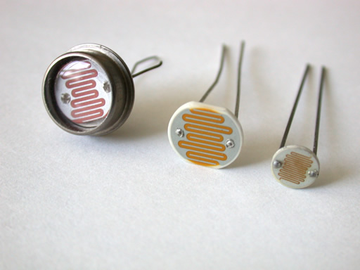
[yours may differ slightly]
Procedure
- A strain gauge is a resistive sensor where the electrical
resistance changes according to the expansion or contraction of
the sensor. You will make the strain gauge
(or use an existing one).
If you are going to make one, you will need
a regular overhead transparency that has been roughed up with
sandpaper and cut into pieces the size of a business card (5cm by
8 to 9 cm). Draw a symmetric pattern with a graphite pencil on
the roughed up side of the card, examples shown below.
Use alligator clips attached to the ends of the strain gauge as
shown above to connect to the probes of a multimeter, so that
you can measure the resistance across the gauge with a meter.
- Measure the resistance of strain gauge at rest on the
bench.
- Carefully pick up the strain gauge by holding the
alligator clip leads close to the clips attached to the
gauge. Do not touch the exposed metal of the clip. Measure
the resistance of the strain gauge with the gauge in a
neutral position, flexed in, and flexed out. Make sure to
note which side of the gauge is the rough side.
- What is the relationship between the three positions of
the strain gauge -- compression, rest, tension -- and the
resistance you measured?
- Carefully pick up the strain gauge by holding the
alligator clip leads close to the clips attached to the
gauge. Do not touch the exposed metal of the clip. Measure
the resistance of the strain gauge as you gently pull on the
leads to put strain on the gauge. As the strain increases
does the resistance of the strain gauge increase or
decrease?
- Remove the strain gauge and clip the two alligator clips
to each other. What is the resistance of the leads?
When you gently pull on the leads does the resistance
change?
Demonstrate your strain gauge to the lab
staff.
- Whenever you use a sensor, the first thing you have to do is
calibrate the sensor. Since the photoresistor is a resistive
sensor, you will measure the resistance when there is no
light shining on the photoresistor and when there is no
obstruction to light shining on the photoresistor (beware of
shadows). These measurements should provide the minimum and
maximum resistance under regular light conditions.
As the light increases does the resistance of the sensor increase
or decrease?
- For this question, use the 5V supply for
Vs.
As discussed in class, sensors can be used in a voltage
divider circuit. For the photoresistor, as the light changes, the
resistance Rsensor changes and therefore Vout changes.
Given your
measurements in the previous question and given the voltage
divider circuit configured as shown below, as the light increases
does Vout increase or decrease? Note: you should answer
this
without constructing the circuit.
- How would the relationship between increasing the light and
Vout change if you switched the locations of
R1 and Rsensor?
[Hint: write out the equations for Vout in terms of
Vs,
R1, and
Rsensor under both configurations.]
- Normally, R1 is selected to give the greatest
difference
between the output voltages when Rsensor is at its maximum
(Rmax) and at its minimum (Rmin).
Theoretically, this
is
calculated using the equation R1 =
√(Rmin x Rmax).
Construct a voltage divider circuit for the photoresistor so that
Vout increases as the light hitting the photoresistor
increases.
Decide which configuration of the voltage divider circuit is
appropriate to meet the specifications. Measure Vout
for the two
lighting extremes. How does this compare with your expected
results?
- In digital logic circuits, anything above 3.5 volts is a
logical '1' and anything below 1.5 volts is sensed as a
logical '0'. If this circuit was intended to drive a
digital logic subcircuit with no light corresponding to logical
'0' and full light corresponding to logical '1',
can you get reliable operation using this voltage divider
circuit? Explain.
Demonstrate your voltage divider circuit to the lab
staff.
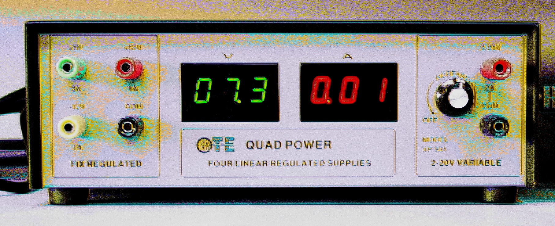
- For this step, you must use the external voltage
supply at your station.
It may look like this:
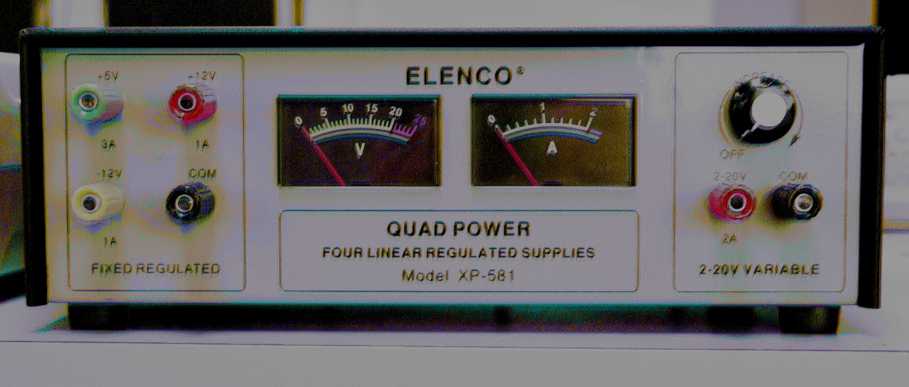
Or like this:
If you don't have one at your
station, temporarily move to a station that has one. The
internal bench
supplies cannot be substituted for the external supply.
- Turn the supply on.
- Adjust the voltage knob on the variable supply to 5 volts.
- Is the variable supply equal to the fixed 5V supply?
Put a voltmeter across the terminals for
each supply and fine tune the variable supply voltage to the
measured voltage of the fixed supply.
Do not touch the metal part of the meter probe with
your
hands!
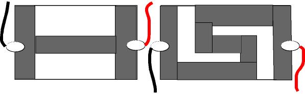
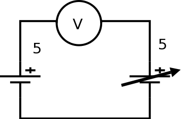
Are they really equal? Although both supplies have been set
to the same voltage, one supply will be set higher than the
other. Set
up a null measurement circuit (shown below) by
inserting a volt meter between the two positive power
supply terminals.
- Are the supplies 'balanced'?
- Which one is higher?
- Can you balance the supplies more accurately using the
null measurement circuit configuration?
Demonstrate the concept of null measurement to the
lab
staff.
- One application of the Wheatstone bridge circuit is to
measure an unknown resistance in terms of three known
resistances. The same circuit can be used to obtain a precise
measurement of a resistance. In fact, meters use an internal
Wheatstone bridge to measure the value of a resistor in an
electric circuit.
The bridge shown below has two resistor branches: the left
branch with resistors R1 and R2 is the
reference
branch and the right branch with R3 and an
unknown
resistor Rx is the evaluation branch.
[Normally, for
this application the resistor Rx would not be
measurable with a
normal meter. Since we are interested in investigating the
characteristics of the bridge circuit, all resistances will be
measurable with a normal meter.]
As discussed in class, if the bridge circuit is in
'balance', the voltage between the midpoints
of the two branches is zero (at the point noted as
'Meter') and the branches are voltage dividers where
V2
= Vx.
Construct a Wheatstone bridge with four resistors of the same
magnitude but different values. Use a variable resistor for
R3
and use it to balance the circuit (voltmeter at location
'Meter' should indicate 0 volts).
- Measure the resistances of R1, R2,
and R3.
- Calculate Rx. [Hint: what is the relationship
between the
resistances when the bridge is balanced?]
- Measure Rx to verify.
The Wheatstone bridge can be direct-reading, i.e. the
value given by R3 is the same as Rx
allowing the
value of Rx to
the read directly from R3. If the Wheatstone bridge
is to be
direct-reading, what values are required for R1 and
R2?
Demonstrate your Wheatstone bridge to the lab staff.
Explain
how the concept of null measurement from the previous step is
the basis of the operation of the bridge circuit.
- Construct a Wheatstone bridge circuit to compare two
photoresistors at no light and full light conditions. For optimal
operation keep all resistances of the same order of
magnitude.
- Where in the bridge circuit will you locate your
photoresistors?
- What do the other two resistors have to be to satisfy null
measurement conditions? For optimum operation, the two
resistors in a branch should be of the same order of
magnitude.
- Are the photoresistors identical (hardly likely)?
- Is the range of one shifted from the range of the
other?
- Is the range of one contained within the range of the
other? (In other words, is the minimum of one higher than the
minimum of the other while its maximum is lower than the maximum
of the other?)
Demonstrate your Wheatstone bridge to the lab staff.
Explain the relationship between the two photoresistors and
demonstrate your experimental procedure.
Before you leave the lab, have the lab
supervisor sign your lab notebook immediately after your last
entry.
Wilfrid Laurier University
© 2019 Wilfrid Laurier University


