Pages created and updated by
Terry Sturtevant
Date Posted:
May 12, 2017
When drawing digital circuits, especially ones with several outputs, there are some ways that you can make a circuit easier to draw and follow. Here's an example of a layout for a typical SOP (i.e. sum-of-products) layout:
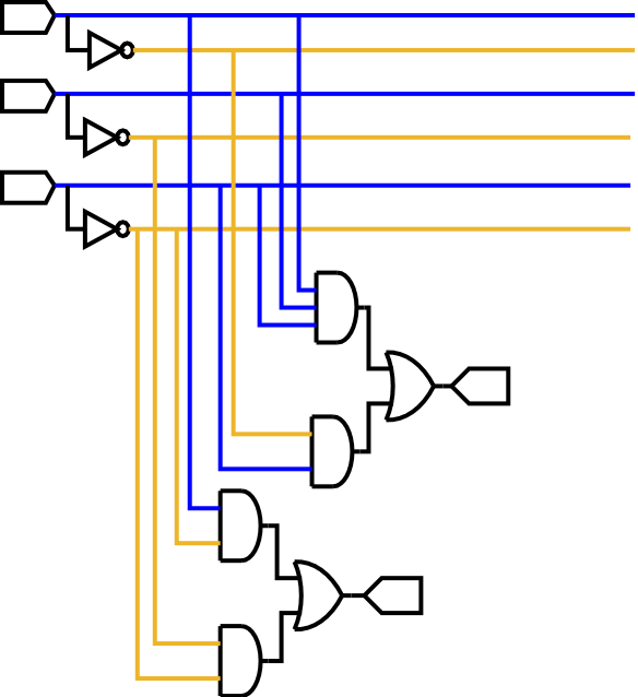
With all of the inputs on the upper left and outputs on the lower right, it makes it easy
to see the flow of logic.
Also, the inverters on each of the input signals at the beginning mean that both signals
and their complements are available anywhere.
The dropdown lines for signals make it easy to see which signals are input to each AND gate.
By copying a simple AND-OR bock, it's easy to fit several outputs on the page just by starting
the first one far enough down. If desired, you can extend all of the outputs to the right of the diagram
so that they are aligned.
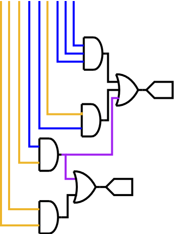
It's fairly common for certain product terms to show up in for than one output equation. Remember that in a drawing, a product term represents a gate. So in a drawing you can simply take the output representing the repeated term and feed it into each OR gate that uses it, rather than redrawing it each time.
Occasionally when choosing gates, your choices don't have exactly the right number of inputs. This is easy to handle if you have gates with more inputs than required.
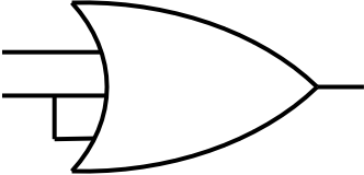
Whether the gate is an AND,OR, NAND, or NOR, tying an unused input to one of the used ones will serve the purpose. There is ONE type of gate where this would be a problem. What is it?


![]()
Wilfrid Laurier University
© 2019 Wilfrid Laurier University