In this lab you will design a simple Binary (BCD)-to-Decimal decoder. The schematic diagram will not be given; you will need to figure out your circuit layout and how to connect the circuit components.
You will need to make some choices about what device you will use to input to your decoder. You can either use the encoder circuit you wired in the previous lab or use the dipswitch circuit you wired in the digital logic lab. Hint: Examine carefully the truth table of the decoder to see what kind of input it accepts (high/low).
Use the 7-segment display to display the output (decimal numbers from 0 to 9).
One decoder SN74LS48N
One 7- segment Display
One inverter (not) 7404 (if needed).
One DIP switch (if needed).
Seven 470 Ohm resistors
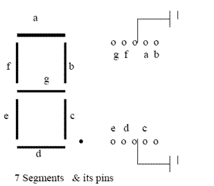
In the figure is a 7-segment display. These segments, labeled a to g, can be turned on individually, or they can all be controlled by a 7448 BCD to decimal decoder. This chip receives 4 inputs, labeled A to D, and lights up the appropriate segments of the display.
Examine the pin layout of a 7-segment display used in the lab before you start wiring. Your display has a common-cathode that requires the driver (decoder) to provide a high-level voltage to activate a segment. The common pin is connected internally and only needs to be grounded from one side.
Information about 7448 and 7404 ICs check the datasheet at this link.
http://rabbit.eng.miami.edu/info/datasheets/