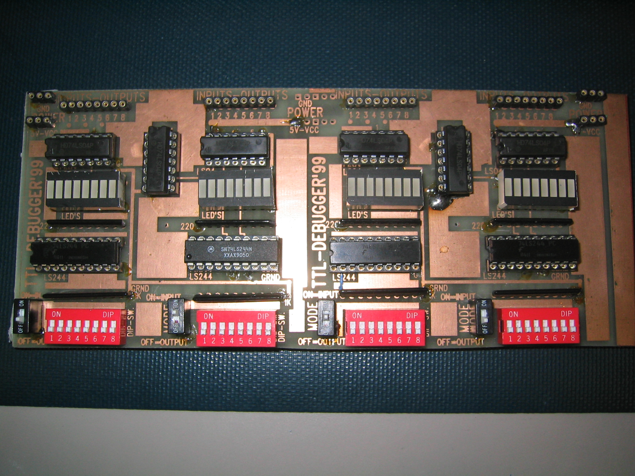
You will use the debugger board (see below) to test whether your circuit is working or not.
The debugger board is set up with four banks of eight signals. Each bank can be configured to either "display" logic levels in your circuit or to "control" logic levels in your circuit. In "display" mode, you can connect a signal to its corresponding connection on the debugger board and the LED will be ON if the signal is HIGH and OFF if it is LOW.
Note: The debugger board has TTL gates on its input. These gates, like most TTL gates, tend to float HIGH if unconnected. Thus, if you have nothing connected to a pin in a bank set for "display" mode, the LED will usually be ON. NO connection does NOT mean LOW; pins MUST be tied LOW if you want to ensure that they are LOW.
In "control" mode, the DIP switches for a bank of connectors will control the logic level on the pins.
Note: Make sure that you do not try and have two different things trying to control the same signal. For instance, only use the debugger board in "control" mode to connect to inputs of your circuit which are not connected to anything else.
Switching a bank from one mode to the other is accomplished either by a single DIP switch or by a jumper. (You can tell which mode you're in by whether the bank of DIP switches change the LEDS. If so, you're in "control" mode. If not, you're in "display" mode. The circuits on the debugger board need power and ground to work, so make sure they are connected.
Here are a few important rules to follow when handling ICs during debuging:
Your circuit will probably not work the very first time.
Therefore, trouble-shooting is a basic skill that you will have to learn.
The followings are a list of helpful suggestions:
Ensure youre are using the right IC and placing in the right way on the breadboard.
Start trouble-shooting at the point, at which the logic/voltage value is wrong in the circuit
and continue to check your circuit backward, making sure that at each point the logic/voltage
value agrees with your desired value.
Construct your circuit neatly. Use appropriate length wires for connections,
i.e. use short wires for short distance connections.
Your circuit should not look like a bowl of spaghetti:
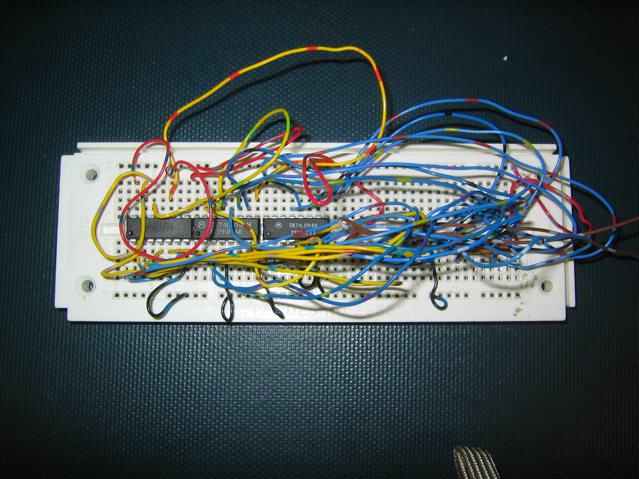
better look will be:
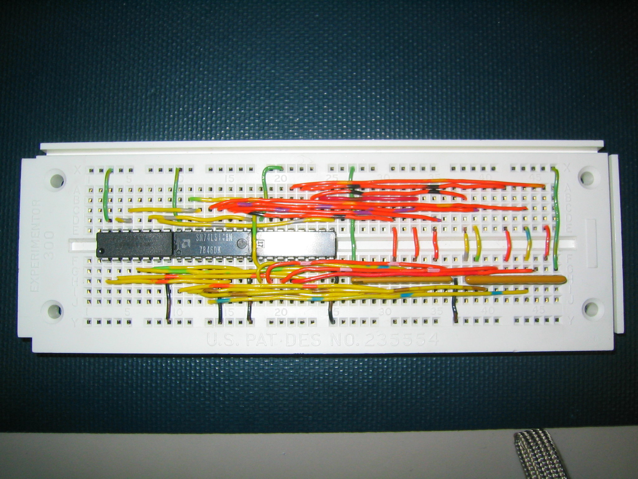 .
.
Check IC insertion to make sure all the pins are in the holes correctly and the IC does not
have any missing legs.
Make sure that the power and the ground are properly connected to all IC's before power up your ciruit.
DO NOT strip wire ends longer than 1/4" (1/2 cm) and jam long bare ends into the breadboard holes. This will
cause shorts and ruin the board.
DO NOT short the power supply to the ground in the breadboard. This will cause the permanent chip damage.
DO NOT connect an output of any gate to the output of another gate, to a switch, to the power (+5V),
or to the ground. These situations will cause excessive currents and result in the permanent
damage to the chip.