CP480 Wireless Communication and Networks Laboratory
Arduino with
NRF24L01 module
Background
The NRF24L01 is a low cost wireless communication module that can be
used with single board compuiters like the Arduino and the
Raspberry Pi. While it uses the 2.5GHz band, it requires no wifi
or other infrastructure.
Objectives
- To become familiar with the SPI interface on the Arduino.
- To use the NRF24L01 module for simple wireless
communication.
Equipment
- Arduino Uno board
- NRF24L01 module
- Linksprite LCD display shield (optional)
Procedure
Setup
-
Note: If you choose pins carefully, you can keep the
LCD shield connected while attaching the wireless module.
Specifically, the analog input pins on the Arduino can also be used as
regular digital I/O pins. The names are A0, A1, etc.
(Remember A0 is used by the LCD shield.)

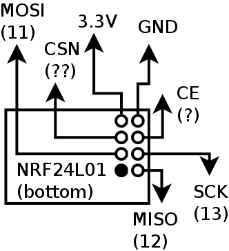
Wire up the Arduino with the module.
Note: The wireless transceiver need 3.3V for power, not 5V,
but the pins are 5V-tolerant so they can be connected directly to
the This is indicated on the schematic diagram.
documentation
of RF24 library
-
Demonstrate the program working.
- Disconnect the Arduino from the USB cable and attach the LCD
shield.
- Reconnect the USB cable
- Create a new sketch using the sample
code provided.
Demonstrate the program working.
- Pin D10 is used by the shield to control the backlight.
Connect the pin to GROUND to see the effect.
Modify your sketch by making pin 10 an output, and when the
"Down" key is pressed make it LOW, and when the "UP" key is
pressed, make it HIGH. (See the Blink sketch for examples of how
to make a pin HIGH or LOW.)
Demonstrate the program working.
-
Look at the postlab task, and complete as much of it as possible
before you leave the lab.
Wilfrid Laurier University
© 2019 Wilfrid Laurier University


