CP316: Microprocessor Systems and Interfacing
Testing Hardware Timing
Objectives
The speed with which a microprocessor or microcontroller communicates
with hardware is dependent on many factors. One obvious factor is the
clock speed, however this is often not the most
important factor.
Equipment
Procedure
Raspberry Pi Manual Pin Toggling
- Connect the Raspberry Pi with the serial monitor.
- Download gpio_test_basic.py.
- Connect the oscilloscope to the output pin.
- Run the program to see that the square wave appears on the scope.
- Comment out the delay instructions in the program and rerun it so
you can see the maximum frequency that can be produced.
Sketch the output, and note the oscilloscope settings.
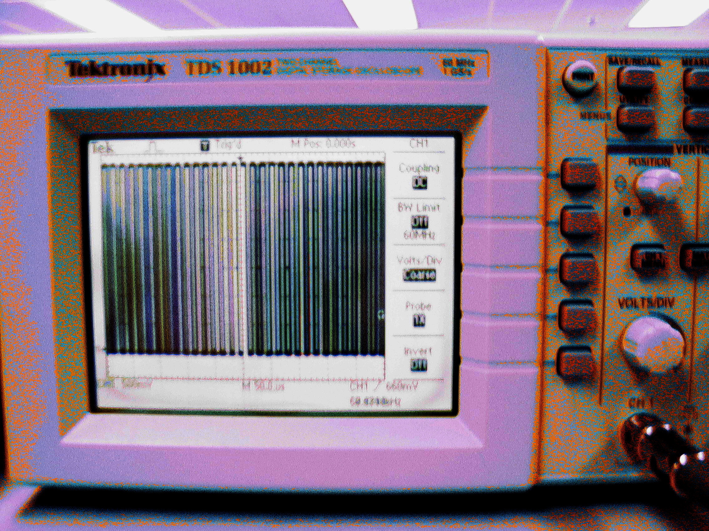
Is the output sharp or fuzzy? What does this tell you about the
stability of the timing?
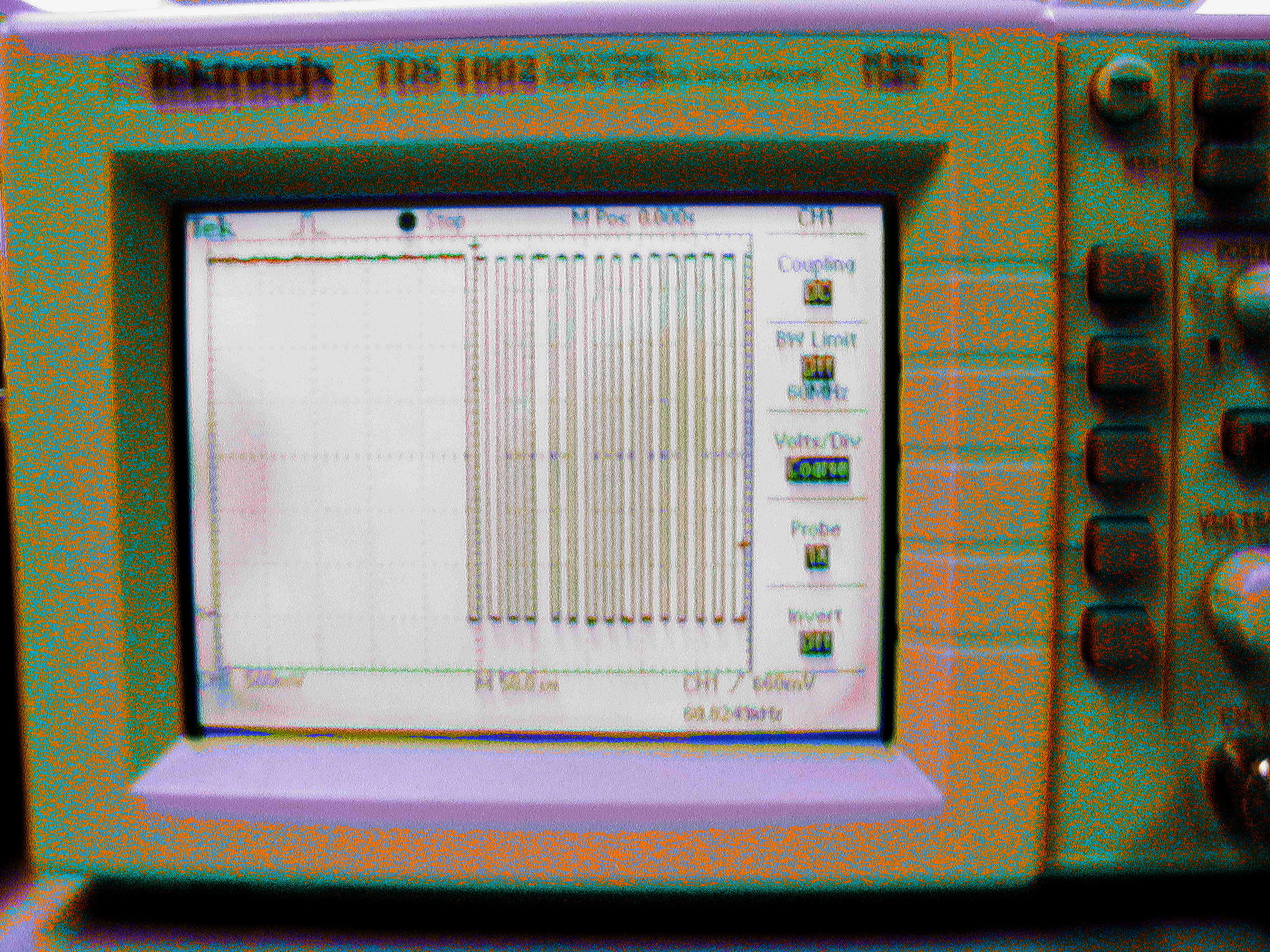
- Press the Run/Stop button on the oscilloscope to freeze
the image, and note how consistent the pulses are. Repeat this 5 or 6
times to find the maximum variation between pulses that you observe.
Sketch the output, and note the oscilloscope settings.
Demonstration - demonstrate the screen showing the
variation.
Because the operating system is scheduling several tasks, your program
will be suspended periodically, which will result in occasional long
pulses.
Raspberry Pi PWM Operation
- Download pwm_test_continuous.py
.
- Change the frequency to the maximum frequency observed previously,
run the program and observe the output.
- As before, press the Run/Stop button on the oscilloscope
to freeze
the image, and note how consistent the pulses are. Repeat this 5 or 6
times to find the maximum variation between pulses that you observe.
Sketch the output, and note the oscilloscope settings.
Demonstration - demonstrate the screen showing the
variation.
Does the PWM capability avoid the problem of manual toggling of pins?
What does that tell you about whether PWM is a feature of the hardware
or the software?
- Increase the frequency, and see what maximum frequency you can
achieve using the PWM feature.
- When you're done, shutdown and put away the Pi.
Arduino blink program
- Connect the Arduino board.
- From the Examples, load the Blink sketch.
- Connect the oscilloscope to output pin 13.
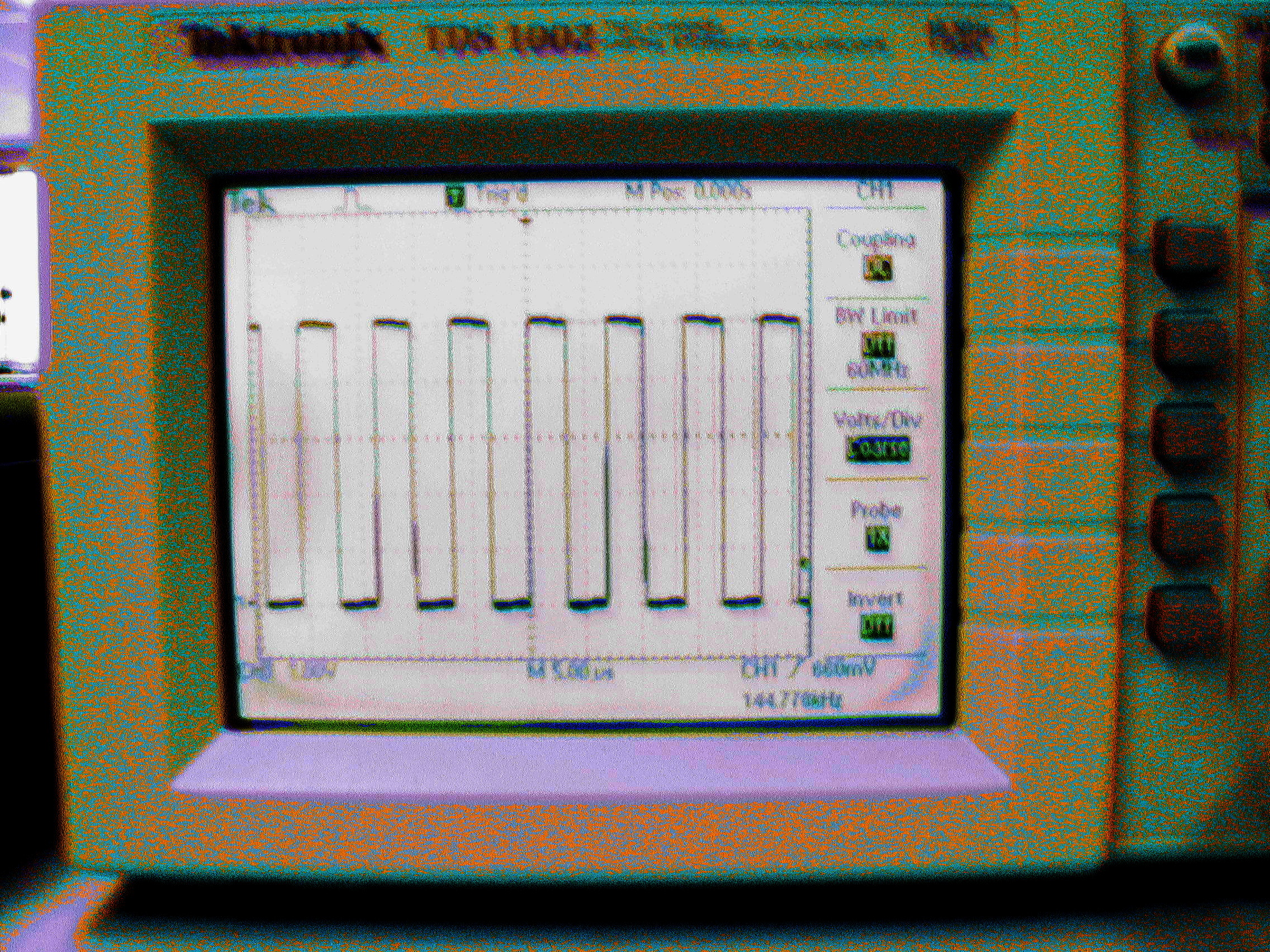
- Run the program to see that the square wave appears on the scope.
- Comment out the delay instructions in the program and rerun it so
you can see the maximum frequency that can be produced.
Sketch the output, and note the oscilloscope settings.
- Press the Run/Stop button on the oscilloscope to freeze
the image, and note how consistent the pulses are. Repeat this 5 or 6
times to find the maximum variation between pulses that you observe.
Sketch the output, and note the oscilloscope settings.
Demonstration - demonstrate the screen showing the
variation.
Because there is no operating system,
your program
is the only task running.
Arduino blinkfast program - using low level
features
- Create a new sketch, and download the
Blinkfast
sketch.
- Run the program to see that the square wave appears on the scope.
- Comment out the delay instructions in the program and rerun it so
you can see the maximum frequency that can be produced.
Sketch the output, and note the oscilloscope settings.
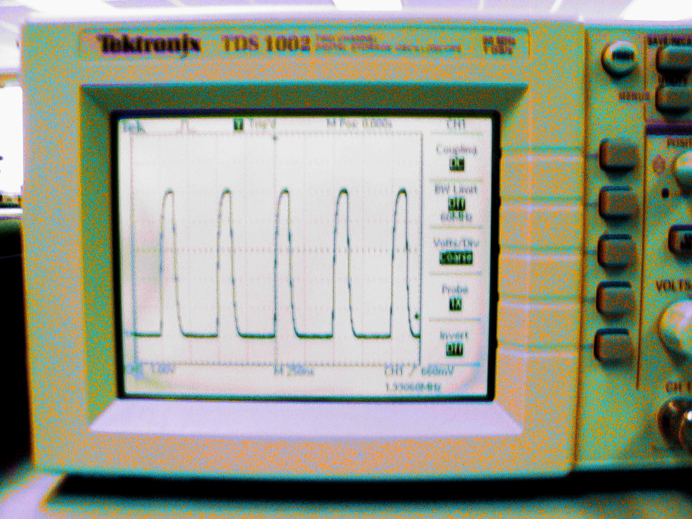
Is the duty cycle 50%? If not, what does that mean about the
assembly language code?
- Press the Run/Stop button on the oscilloscope to freeze
the image, and note how consistent the pulses are. Repeat this 5 or 6
times to find the maximum variation between pulses that you observe.
Sketch the output, and note the oscilloscope settings.
Demonstration - demonstrate the screen showing the
variation.
Because there is no operating system,
your program
is the only task running.
Inline assembly language
It is possible in the Arduino IDE to insert assembly language commands,
as described in
this tutorial.
- Insert NOP instructions into the blinkfast code to make the output
have a 50% duty cycle.
Demonstration - demonstrate the revised code running.
Arduino diasassembly
The Arduino IDE contains all of the tools necessary to see the
actual assembly language code of a compiled program.
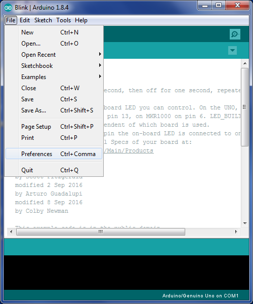
-
Open the File menu
and choose Preferences.
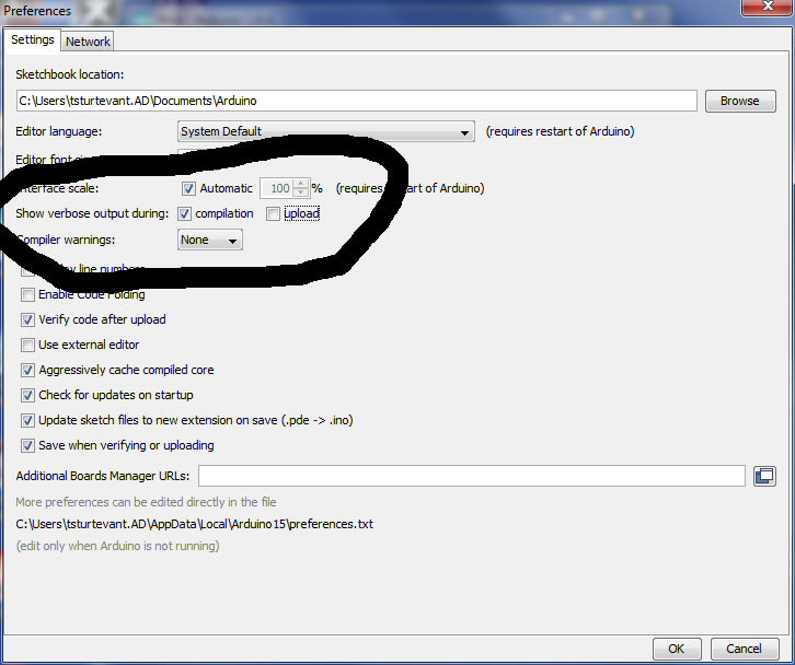
-
Choose the verbose output option.
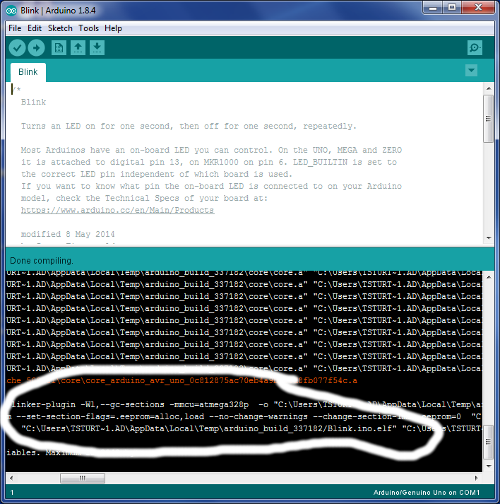
-
File the location of the elf file when you compile the
program.
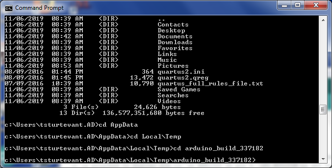
-
Change to the directory containing the elf file. (Note how your
username
may not show up as expected when it shows the path.)
-
Run the command to dissasemble the elf file.
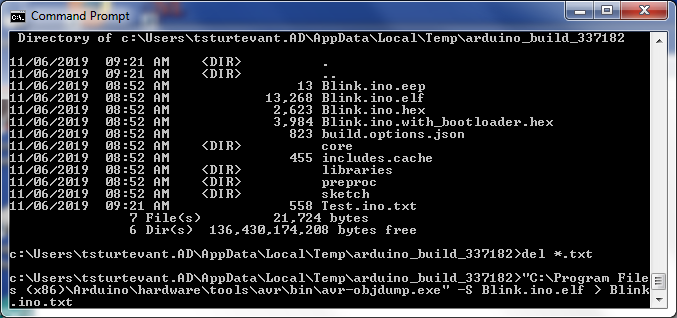
-
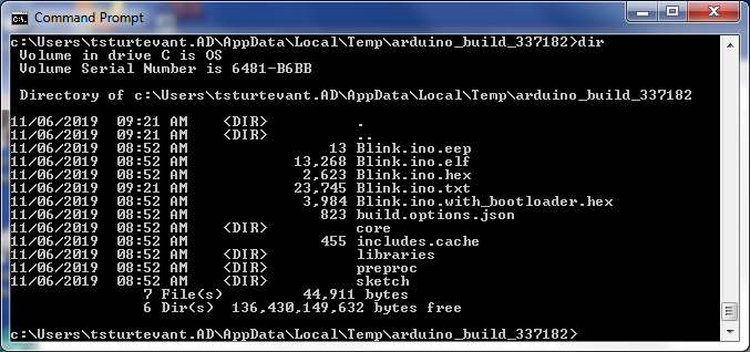
Note the dissasembled (txt) file is much bigger than the
elf
file.
-
Open the dissasembled (txt) file in any text editor.
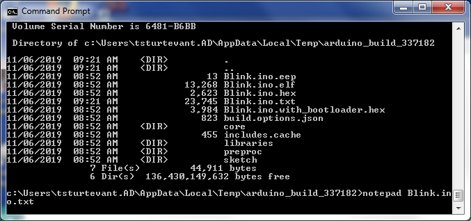
-
It should look like this:
Blink.ino.txt
Search for void loop() to see where your code starts.
Wilfrid Laurier University
© 2019 Wilfrid Laurier University


