|
Note 1: There are other options, but these are the most useful ones.
|
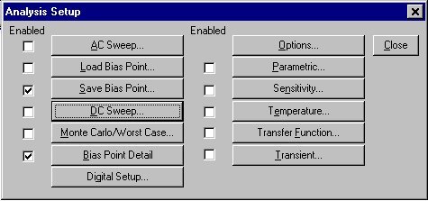
To open the analysis menu click on the ![]() button.
button.
i. VDC
- This is your basic direct current voltage source that simulates a simple battery and allows you to specify the voltage value.
ii. VAC
- A few things to note about the alternating current source, first PSpice takes it to be a sine source, so if you want to simulate a cosine wave you need to add (or subtract) a 90° phase shift. There are three values which PSpice will allow you to alter, these being:
- ACMAG which is the RMS value of the voltage.
- DC which is the DC offset voltage
- ACPHASE which is the phase angle of the voltage
- Note that the phase angle if left unspecified will be set by default to 0°
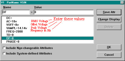
iii. VSIN
- The SIN type of source is actually a damped sine with time delay, phase shift and a DC offset. If you want to run a transient analysis you need to use the VSIN see how AC will effect your circuit over time. Do not use this type of source for a phasor or frequency sweep analysis, VAC would be appropriate for that.
- DC the DC component of the sine wave
- AC the AC value of the sine wave
- Voff is the DC offset value. It should be set to zero if you need a pure sinusoid.
- Vamplitude is the undamped amplitude of the sinusoid; i.e., the peak value measured from zero if there were no DC offset value.
- FREQ is the frequency in Hz of the sinusoid.
- TD is the time delay in seconds. Set this to zero for the normal sinusoid.
- DF is the damping factor. Also set this to zero for the normal sinusoid.
- PHASE is the phase advance in degrees. Set this to 90 if you need a cosine wave form.
- Note that the normal usage of this source type is to set Voff, TD and DF to zero as this will give you a 'nice' sine wave.
iv. VPULSE
- The VPULSE is often used for a transient simulation of a circuit where we want to make it act like a square wave source. It should never be used in a frequency response study because PSpice assumes it is in the time domain, and therefore your probe plot will give you inaccurate results.
- DC the DC component of the wave.
- AC the AC component of the wave.
- V1 is the value when the pulse is not "on." So for a square wave, the value when the wave is 'low'. This can be zero or negative as required. For a pulsed current source, the units would be "amps" instead of "volts."
- V2 is the value when the pulse is fully turned 'on'. This can also be zero or negative. (Obviously, V1 and V2 should not be equal.) Again, the units would be "amps" if this were a current pulse.
- TD is the time delay. The default units are seconds. The time delay may be zero, but not negative.
- TR is the rise time of the pulse. PSpice allows this value to be zero, but zero rise time may cause convergence problems in some transient analysis simulations. The default units are seconds.
- TF is the fall time in seconds of the pulse.
- TW is the pulse width. This is the time in seconds that the pulse is fully on.
- PER is the period and is the total time in seconds of the pulse.
- This is a very important source for us because we do a lot of work on with the square wave on the wave generator to see how various components and circuits respond to it.
v. PWL (Piece-Wise Linear)
- The PWL source is a Piece Wise Linear function that you can use to create a wave form consisting of straight line segments drawn by linear interpolation between points that you define. Since you can use as many points as you want, you can create a very complex wave form This source type can be a voltage source or a current source.
- The syntax for this source type is flexible and has several optional parameters. The required parameters are two-dimensional points consisting of a time value and a voltage (or current) value. There can be many of these data pairs, but the time values must be in ascending order, and the intervals between time values need not be regular.
- The two optional parameters are "DC" and "AC." The use of an AC parameter with this source is not very well documented and because this source is intended for use with a transient analysis any AC value would be ignored.
and fill it in with the Time Step that you want your 'clock' to have. This Time Step value is the your 'clock' pulse. There are various ways you can fill out the command prompts, one way is to do it as shown in the picture, however here are some simple commands that will allow you to do a range of simulations:
- REPEAT FOREVER, to simulate a real clock
- REPEAT <n> TIMES
- END REPEAT
- <<time>> INCR <<value>>
- <<time>> DECR <<value>>
- for <<value>> you can use, 0,1,R(rising), F(falling), X(unknown), or Z(high impedance)